 |
| home |
| Research |
| Publications |
| CV |
RESEARCH: George M. Holzwarth
MEDIC: motion-enhanced differential interference microscopy
PM-DIC: polarization-modulated differential interference microscopy
|
RESEARCH: George M. HolzwarthMEDIC: motion-enhanced differential interference microscopy PM-DIC: polarization-modulated differential interference microscopy
|
Vesicles in live PC12 neurites
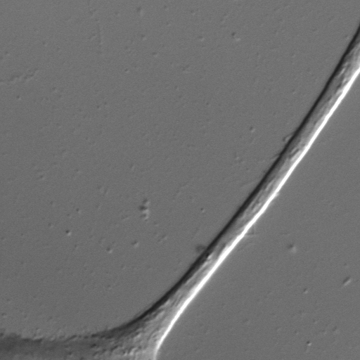
Measurements of the velocities of vesicles in neurites of live PC12 cells show that 1-4 motors are required for anterograde transport on microtubules The force required to move vesicles in live cells is 4-15 pN, exceeding the 7-pN stall force of a single kinesins in vitro.The Figure below shows a wide-field 60X DIC image of a PC12 cell (Image size: 55 x 55 microns^2. Vesicles are barely detectable in this image.
Using MEDIC (motion-enhanced DIC), we track vesicles moving in such PC12 neurites. MEDIC works by averaging the last 16 images to define a background image. Stationary features such the neurite are retained but moving objects such as vesicles are largely eliminated from the background image. The background image, which is continually updated, is then subtracted from the raw incoming images to give a background subtracted DIC image, as shown in the figure below:
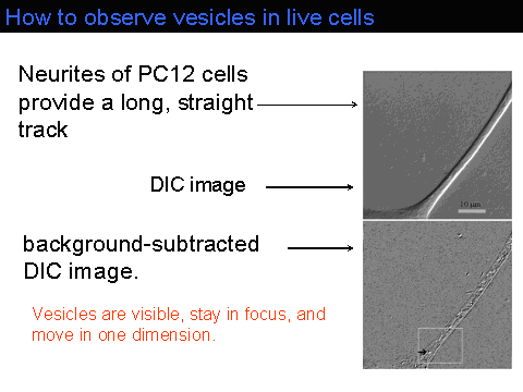
The contrast in the background-subtracted image can then be aggressively enhanced. A stream of such images reveals rapidly moving vesicles (see movie in QuickTime(7.45MB) or MPEG-1(1.75MB)). Individual vesicles do not move at constant velocity in PC12 neurites. Rather, they move at one speed for 1-2 s, then move at a different speed. A histogram of the scaled vesicle velocities exhibits 4 peaks.
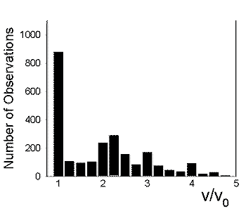
We believe that these peaks arise when 1, 2, 3, or 4 motors pull a single vesicle.
The force required to move the vesicles at the observed velocities is determined from Stokes' Law, using measured values of the viscosity of the PC12 cytoplasm as sensed by these vesicles. This viscosity is determined by analyzing the Brownian motion of unbound vesicles in PC12 cells, using Mason's Generalized Stokes-Einstein method (details in Hill, Plaza, Bonin, and Holzwarth, Eur Biophys Jl 33, 623-632 (2004): pdf).
Vesicle transport in live chick motoneurons
In collaboration with Carol Milligan and Jason Newbern of the WFU Medical School, and with Jed Macosko, we are measuring the velocities of vesicles in primary cultures of chick motoneurons. This project has two goals. First, do vesicles in a primary culture of neurons exceed the 800 nm/s ceiling established for kinesin in vitro? Second, can we detect the effects of multiple motors in a primary culture? We have tracked both anterograde and retrograde vesicles in cultured motoneurons and observe velocities substantially greater than the zero-load velocities observed for kinesin and dynein in vitro.
In vitro transport
We are determining force-velocity curves
in vitro when 1, 2, or 3 kinesins drive a single load. The velocity-force
relation of
one kinesin motor is
well understood when the motor is in solution and the viscous work load
on it is small.
However, within a cell, the viscoelastic drag force opposing the
motor
is
at
least 100 times greater, which makes it likely that 2-5 motors
are required to pull a single vesicle. Quantitative velocity-force curves
have been
obtained for
1 kinesin but not for the 2, 3, or more active motors actually
needed to pull a single load in vivo, and qualitative data on the effect
of multiple motors
are contradictory. We hypothesize that 2 or more motors pulling
a
single cargo will share the load equally. As a result, if the velocity-force
curve for 1 kinesin is v1(F), the velocity-force function v2(F)
for two
kinesins will be v1(F/2),
v3(F)= v1(F/3), etc. The specific aim of this project is to measure
velocity-force curves for 1, 2, and 3 kinesins over a physiologically
realistic force
range, 0-20 pN.
MEDIC:
Motion-enhanced DIC microscopy is a digital version of video-enhanced
DIC microscopy,which was used with analog
video cameras by Allen and by Inoue in the late 1980's. It takes advantage
of the 12 or 14-bit grayscale information of modern digital cameras and
continuously-updates the background image. A flow chart of the system is
given below: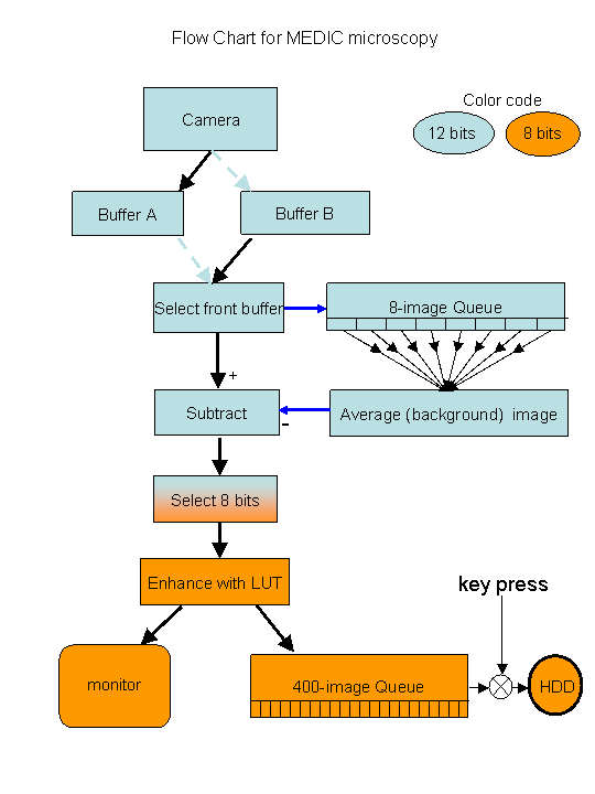
Polarization-modulated DIC microscopy. Contrast can be improved in DIC microscopy by inserting a thin, computer-controlled liquid-crystal polarization modulator into a standard DIC microscope [G. Holzwarth, S.C. Webb, D.J. Kubinski, and Nina S. Allen, J. Microscopy, December, 1997, p249-254 ; Holzwarth G, Hill DB, and McLaughlin EB, Applied Optics 39, 6288-94(2000).]. By switching the polarization of the incident light by 90deg in alternate video frames with a liquid crystal modulator, the contrast signal of unstained biological specimens is increased by a factor of two, relative to standard video-enhanced DIC. Switching the polarization changes image highlights into shadows and vice versa. By subtracting alternate frames, a difference DIC image is created in which contrast is doubled while image defects and noise tend to cancel. The method can take full advantage of the extended dynamic range and more precise digitization of modern CCD cameras as well as the increased speed of modern frame processors. Because the modulator can be synchronized with frame acquisition by the camera, electronic phase sensitive detection can be carried out efficiently by frame buffer operations. The need for a background image(Allen and Allen, 1983; Salmon, 1995), which requires some operator skill for best implementation, is eliminated. A DIC microscope with modulator installed is shown in Figure 1 below. An inexpensive ferroelectric liquid-crystal modulator with 25 mm aperture and 5 mm thickness can be installed into a swing-out holder which fits between the polarizer and the condenser. It is oriented so that, in one of its two states, the emergent light is polarized in the x-direction, the standard direction. When in the other state, the light transmitted by the modulator is polarized along y. The electronic controller for the waveplate must be synchronized with the camera to flip the polarization between x and y at frame rates.
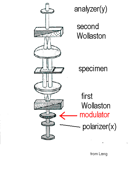
Figure 1. DIC microscope with modulator between the polarizer and the first Nomarski-Wollaston prism.(modified from Lang,1968).
___________________________________________________________________________________________________
How polarization-modulation changes contrast
The intensity of the light transmitted by the analyzer in a normal DIC microscope is given by
![]()
where D is the total phase shift of one beam with respect to the other, G is the offset introduced by the second Wollaston, and d is the phase shift introduced by the sample. If instead the modulator switches the incident light from x to y, then

The polarizations of the light in each beam are shown in Figure 2 for normal(x) and switched(y)polarizations.
_________________________________________________________
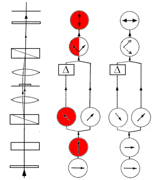
Y X
Figure 2. Ray Paths and Polarizations in PM-DIC. Note the 180° phase shift of the light in the left beam caused by changing the polarization from x to y. (Diagram adapted from Spencer, 1982)
_________________________________________________________
An embedded phase object within the sample will normally have a highlight on its upper left edge and a shadow at its lower right edge, as explained in Fig. 3, right-hand inset, This gives the apparent 3D effect characteristic of DIC images.
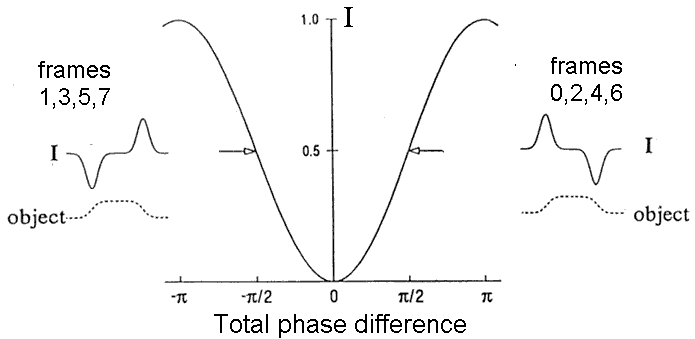
Figure 3. Generation of image contrast. The main curve shows the relative intensity I/I0 = sin2(D / 2 ) as a function of the total phase shift D = G + d. The inset on the right corresponds to normal DIC with x-polarized light. The phase object shown has d > 0 on its left edge and d < 0 on its right edge. The offset G is set to + p / 2 . This gives an "operating point" on the right side of the null in the sin2(D / 2 ) curve. As a consequence, I> IB on the left edge of the object, but I< IB on the right edge of the object, giving standard shading. In a real-time system, images 0,2,4, etc would have this shading.The inset on the left describes what happens if the input light is y-polarized, but offset G remains p / 2 and the spatial dependence of d caused by the sample is unchanged. Because of the change in polarization, the "operating point" is now on the left side of the null in the sin2(D / 2 ) curve, that is, D = - p + G + d . Therefore, the intensity on the left edge of the object is less than the intensity at the right edge. This leads to inverted shading and applies to images 1,3,5,7, etc
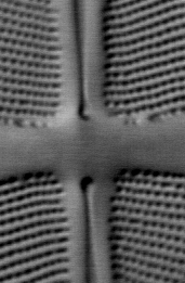
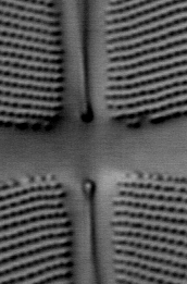
The three images in Fig 4 below illustrate the principle of polarization modulation.
 |
 |
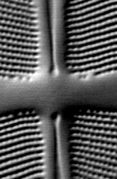 |
Figure 4. Images of a small region of the diatom Frustulia rhomboides obtained
by polarization-modulated DIC microscopy.
LEFT: DIC image obtained with x-polarized incident light
CENTER: DIC image obtained with y-polarized incident light.
RIGHT: DICx - DICy image
______________________________________________
We have implemented real-time, 30 frames/s PM-DIC with 12-bit
scientific-grade cooled CCD camera and an image-processor
board from Matrox. Only the difference images
PM X -
PM-Y is displayed on a
monitor and
updated at
30 fps. Once
installed,
PM-DIC is simpler to
use than VE-DIC, because background subtraction
is done automatically. This frees the microscopist to concentrate on
the specimen.
Also, the small intensity differences which make up the image are doubled
in PM-DIC, revealing more subtle features of the specimen.