Contrast can be improved in DIC microscopy by inserting a thin, computer-controlled liquid-crystal polarization modulator into a standard DIC microscope [G. Holzwarth, S.C. Webb, D.J. Kubinski, and Nina S. Allen, J. Microscopy, December, 1997, p249-254 ; Holzwarth G, Hill DB, and McLaughlin EB, "Polarization-modulated DIC microscopy with a variable retarder", Applied Optics 39, 6288-94(2000).]. By switching the polarization of the incident light by 90° in alternate video frames with a ferroelectric liquid crystal modulator, the contrast signal of unstained biological specimens is increased by a factor of two, relative to "standard" video-enhanced DIC. Switching the polarization changes image highlights into shadows and vice versa. By subtracting alternate frames, a difference DIC image is created in which contrast is doubled while image defects and noise tend to cancel. The method can take full advantage of the extended dynamic range and more precise digitization of modern CCD cameras as well as the increased speed of modern frame processors. Because the modulator can be synchronized with frame acquisition by the camera, electronic phase sensitive detection can be carried out efficiently by frame buffer operations. The need for a background image(Allen & Allen, 1983; Salmon, 1995), which requires some operator skill for best implementation, is eliminated.
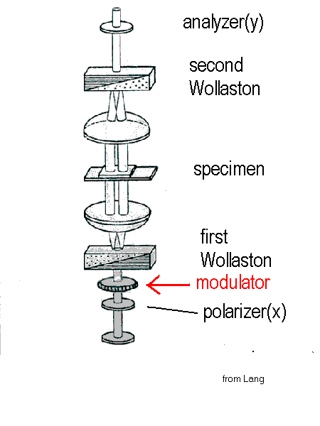
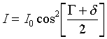
A DIC microscope with modulator installed is shown in Figure 1 below. An inexpensive ferroelectric liquid-crystal modulator with 25 mm aperture and 5 mm thickness can be installed into a swing-out holder which fits between the polarizer and the condenser. It is oriented so that, in one of its two states, the emergent light is polarized in the x-direction, the standard direction. When in the other state, the light transmitted by the modulator is polarized along y. The electronic controller for the waveplate must be synchronized with the camera to flip the polarization between x and y at frame rates.
Figure 1. DIC microscope with modulator between the polarizer and the first Nomarski-Wollaston prism.(modified from Lang,1968).
How polarization-modulation changes contrast
The intensity of the light transmitted by the analyzer in a normal DIC microscope is given by
![]() (1).
(1).
where D is the total phase shift of one beam with respect to the other, G is the offset introduced by the second Wollaston, and d is the phase shift introduced by the sample. If instead the modulator switches the incident light from x to y, then
The polarizations of the light in each beam are shown in Figure 2 for normal(x) and switched(y)polarizations.
_________________________________________________________
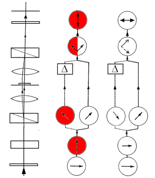
Y X
Figure 2. Ray Paths and Polarizations in PM-DIC. Note the 180° phase shift of the light in the left beam caused by changing the polarization from x to y. (Diagram adapted from Spencer, 1982)
_________________________________________________________
An embedded phase object within the sample will normally have a highlight on its upper left edge and a shadow at its lower right edge, as explained in Fig. 3, right-hand inset, This gives the apparent 3D effect characteristic of DIC images.
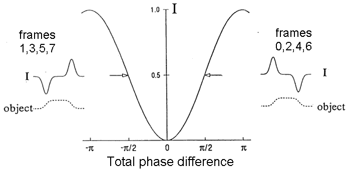
Figure 3. Generation of image contrast. The main curve shows the relative intensity I/I0 = sin2(D / 2 ) as a function of the total phase shift D = G + d. The inset on the right corresponds to normal DIC with x-polarized light. The phase object shown has d > 0 on its left edge and d < 0 on its right edge. The offset G is set to + p / 2 . This gives an "operating point" on the right side of the null in the sin2(D / 2 ) curve. As a consequence, I> IB on the left edge of the object, but I< IB on the right edge of the object, giving standard shading. In a real-time system, images 0,2,4, etc would have this shading.
The inset on the left describes what happens if the input light is y-polarized, but offset G remains p / 2 and the spatial dependence of d caused by the sample is unchanged. Because of the change in polarization, the "operating point" is now on the left side of the null in the sin2(D / 2 ) curve, that is, D = - p + G + d . Therefore, the intensity on the left edge of the object is less than the intensity at the right edge. This leads to inverted shading and applies to images 1,3,5,7, etc.
____________________________________________________________________
Experimental Demonstration
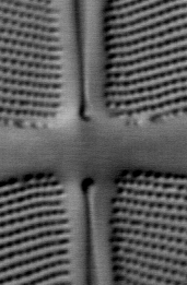
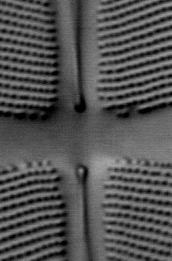
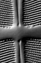
Images of the diatom Frustulia rhomboides collected with polarization modulation are shown in Fig 4.
|
|
|
|
Figure 4. Images of a small region of the diatom Frustulia rhomboides obtained by polarization-modulated DIC microscopy.
LEFT: DIC image obtained with x-polarized incident light
CENTER: DIC image obtained with y-polarized incident light.
RIGHT: DICx - DICy image
______________________________________________
Real-time(30 frames/s) PM-DIC can now be implemented for certain types of RS 170 CCD cameras by Hamamatsu Argus 20 and Dage DSP 2000 processors. With a real-time processor, only the difference images PM X - PM-Y is displayed on a monitor and updated at 30 fps. Once installed, PM-DIC is simpler to use than the current VE-DIC procedure, because background subtraction is done automatically. This frees the microscopist to concentrate on the specimen. Also, the small intensity differences which make up the image are doubled in PM-DIC, revealing more subtle features of the specimen.
Friday, 27-Jan-2006 15:40:49 EST